Digitally Controlled AttenuatorsOffering options that include digital control with up to 4K of resolution, any desired control input slope characteristic, narrowband optimized performance, temperature compensation, video filtering and sub-assembly integration. Operating frequency ranges span from 250 MHz to 40 GHz in up to 9:1 bandwidths. |
 |
Frequency Ranges: From 250 MHz to 40 GHz, any optimized bandwidth is available.
TTL Compatible Logic: Binary logic Digital-to-Analog converter with 8 inputs: Logic ‘1’/BIT = 256 discrete values of attenuation or all Logic ‘0’ = Insertion Loss. Any resolution up to 12 BITs is available.
High Speed Switching: Attenuators listed are measured from any set value to any set value. Switching speeds up to 300 ƞSec on request.
Low DC Power Consumption: Attenuators require ±15 VDC, ±1% @ +100/-50 mA.
Operating Temperature Range: Standard models include temperature compensation in a range from 0° to +50° C. For more severe environments, please consult the factory.
Stable Attenuation: Variation vs. temperature from -55° to +85° C is typically ±10% of the set value. Temperature compensated models are ±2%.
High RF Power Handling: For power levels greater than listed, please consult the factory.
Standard Interfaces: RF port connectors are ‘SMA’ female per MIL-C-39012. Please consult the factory for additional options.
|
Outline Sizes |
||||
|
Size Reference |
‘A’ Dimension IN/CM |
‘B’ Dimension IN/CM |
‘C’ Dimension IN/CM |
‘D’ Dimension IN/CM |
|
1 |
3.00/7.62 |
2.50/6.35 |
2.75/6.99 |
2.25/5.72 |
|
2 & 3 |
2.00/5.08 |
2.50/6.35 |
1.75/4.45 |
2.25/5.72 |
|
4 |
3.00/7.62 |
3.13/7.94 |
2.75/6.99 |
2.88/7.31 |
|
5 |
4.75/12.07 |
4.50/11.43 |
4.50/11.43 |
4.25/10.80 |
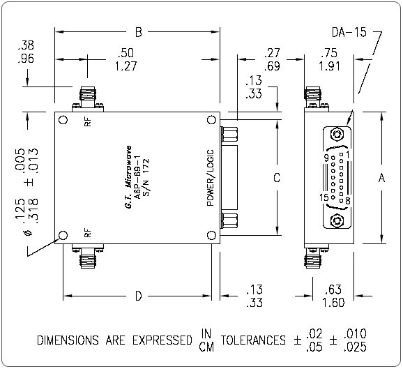
Outline Diagram
|
Power/Logic Connections |
||||
|
Number of BITs |
Logic PIN Assignments |
+15 V PIN |
-15 V PIN |
Ground PIN |
|
8 |
LSB @ 1 to MSB @ 8 |
13 |
14 |
15 |
|
10 |
LSB @ 1 to MSB @ 10 |
13 |
14 |
15 |
|
All unused PINs have no internal connections |
||||
For substantial improvement in performance, ask for optimized narrowband models.
| Electrical Specifications for Digitally Controlled Attenuators | |||||||
|
Frequency Range (GHz) |
Attenuation (dB) |
Flatness vs. Frequency |
Insertion Loss (dB) |
VSWR |
Switching Speed, Harmonic Distortion, Input Power |
Switching Speed, Harmonic Distortion, Input Power |
Size Reference |
|
0.225-2.0 |
32 |
± 3.50 |
4.50 |
2.0:1 |
7.0 µSec Max, 50 dBc Max, +20 dBm Max |
1.0 µSec Max, 30 dBc Max, +5 dBm Max |
5 |
|
64 |
± 6.00 |
||||||
|
80 |
± 8.00 |
||||||
|
0.5-2.0 |
32 |
± 2.00 |
2.50 |
1.8:1 |
1 |
||
|
64 |
± 3.50 |
||||||
|
80 |
± 4.50 |
||||||
|
0.7 – 5.4 |
32 |
± 3.50 |
3.50 |
2.0:1 |
4 |
||
|
64 |
± 4.50 |
||||||
|
80 |
± 5.00 |
2.2:1 |
|||||
|
2.0-8.0 |
32 |
± 2.00 |
2.50 |
1.9:1 |
1.0 µSec Max, 35 dBc Max, +13 dBm Max |
2 |
|
|
64 |
± 2.25 |
||||||
|
80 |
± 2.50 |
||||||
|
6.0-18.0 |
32 |
± 2.00 |
3.25 |
1.9:1 |
1.0 µSec Max, 35 dBc Max, +15 dBm Max |
3 |
|
|
64 |
± 2.25 |
||||||
|
80 |
± 2.50 |
3.50 |
2.0:1 |
||||
|
2.0-18.0 |
32 |
± 2.50 |
4.50 |
2.0:1 |
1.0 µSec Max, 35 dBc Max, +13 dBm Max |
2 |
|
|
64 |
± 4.50 |
2.1:1 |
|||||
|
80 |
± 5.00 |
5.00 |
|||||
|
8.0-26.5 |
32 |
± 2.25 |
3.00 |
2.0:1 |
1.0 µSec Max, 35 dBc Max, +15 dBm Max |
3 |
|
|
16.0-32.0 |
32 |
± 3.00 |
4.00 |
2.0:1 |
|||
|
26.0-40.0 |
32 |
± 2.00 |
4.00 |
2.0:1 |
|||